I started to reverse engineer the Keypad and Display PCB of my WORX Landroid WR142E (Landoird M). While it's not complete, the info could be used to create a custom Keypad for the Landroid or even control it with an Arduino or ESP32, without the need for the Landroid App (There's 5V and 3.3V present on the PCB).
This started, because the Keypad of Landroid started to act funny. Sometime buttons would suddenly stop working and I also experienced "ghost" button presses. Research showed, that the foil Keypad on the Landroid M is supposedly prone to breaking due to watering entering it. So my idea was to replace it with a custom Keypad hidden in the Landroids trunk. Unfortunately it turned out in my case, it wans't the pinpads fault, as I also had the buttons stop working and ghost button presses while having the landroid hooked up to my breadboard and even with no keypad connected at all. So in my case it was related to the Display PCB and the circuit that connects the keypad to the microcontroller.
If you look at the connector on the PCB this the pin layout:
| Nr | Pin | Logic |
|---|---|---|
| 1 | GND | |
| 2 | C3 | 3.3V |
| 3 | C2 | 3.3V |
| 4 | C1 | 3.3V |
| 5 | R3 | 3.3V |
| 6 | R2 | 3.3V |
| 7 | R1 | 3.3V |
| 8 | KON | 20V |
Connect GND to KON to power on the Landroid to "press the power button" (as with the power button, you have to hold if for a second).
Note: If you have the WR142E version (PCB 2.4E) the HAL-Stop button must be connected, or the Microcontroller won't boot (Display just flashes a few times).
The Keypad is a Matrix Keypad, where each button connects a "Column Pin" with a "Row Pin" and the PCB determines the pressed button by finding which two pins are connected. For my Keypad I found that with a button pressed, the resistance goes down to 80 to 100 Ohm, depending on how hard you press. Directly connecting the two pins without a resistor worked fine for me, though.
This is the Button matrix:
| C1 | C2 | C3 | |
|---|---|---|---|
| R1 | START | HOME | BACK |
| R2 | OK | Left (C) | Up (A) |
| R3 | - | Right (D) | Down (B) |
So to press the OK Button, you have to connet Pin C1 with R2.
The Microcontroller on my PCB is labeled: STM32F030K6T6 GQ23M 9C CHN116 12 which reveals that it is an STM32F030K6T6 Micocontroller,
the official data-sheet can be found here:
https://www.st.com/resource/en/datasheet/stm32f030f4.pdf
It seems to be using the LQFP32 32-pin package, which's pinout can be found on page 27.
The Pcb and all components are coated in something, Isopropanol doesn't seem to work, I scratched it off the test pads carefully to do measurements.
I'm assuming the way the keypad is read is quite similiar to the LandLord Keypad (a custom firmware for an older Worx Landroid) https://github.com/Damme/LandLord/blob/master/keypad.c This introduction is also useful for understanding how a matrix keyoad worx: https://www.circuitbasics.com/how-to-set-up-a-keypad-on-an-arduino/.
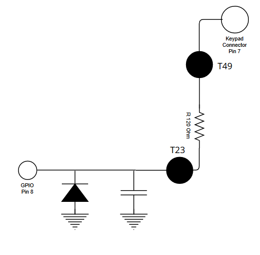
Though the wiring is a bit more complex than in the introduction above, as it contains a filtering circuit:
The Keypad pins are directly connected to pads T46, T47, T51, T48, T50, T49 (C3 to R1).
From there, there's a 100-120 Ohm Resistor to pads T24, T44, T22, T27, T25, T23 (C3 to R1).
Each of these Pads is connected to GND via a diode and to GND via a capacitor.
R1: T23 is connected to Pin 8 (PA2) on the micro controller.
R2: T25 is connected to Pin 9 (PA3) on the micro controller.
R3: T27 is connected to Pin 10 (PA4) on the micro controller.
C1: T22 is connected to Pin 17 (PB1) on the micro controller.
C2: T44 is connected to Pin 25 (PA15) on the micro controller.
C3: T24 is connected to Pin 26 (PB3) on the micro controller.
I measured these voltages, with the battery inserted but the Landroid "turned off" as well as with the Landroid turned on.
- 2.2V on T22, T44 and T24 (C3 to C1) [Should be Pull-Down?]
- 3.3V on T25, T27 (R2, R3) [Likely internal 10k Pull-Up to 3.3V]
- On T23 (R1): It starts out at ~1.5V but drops to 1V after a minute or so on [Likely broken, as it's different from the other rows?]
Which makes me believe, that my issues might be releated to R1 and the lover voltage there. Unfortuantly I don't have a working board to compare it with.
Update: Based on these measurement and my current understand of the circuit, I'm assuming that Pin8 on the Microcontroller was fried, maybe due to a random short in the foil key pad? The R1 line is directly next to the KON line which uses 20V logic (KON is not connected to the micro controller on the Display PCB).
Update 2: I tried many things, the frist thing that seemns to help is adding a 1K Pull-Up to 3.3V to the Pin. Now it starts out at 3.3V and drops to 2.8 when the drop happens. Which is still good enough to not be regocnized as a button press.
Observing the drop:
- 17:30 -> 3.28V
- 17:40 -> 2.8V
- 18:00 -> 2.65V
- 18:15 -> 2.83V
- 18:45 -> 2.94V // there was a short moment where the voltage dropped suddenly to 1.5V and then spiked up and down a few times. It triggered a ghost click, but fixed it self. I removed the diode and cap as part of my debugging and will replace it with my own version