
| Chip Pin | PB | Func | ADC | Digital | PWM | ExtI | USB |
|---|---|---|---|---|---|---|---|
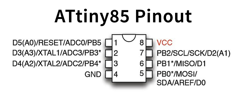
| 1 | PB5 | Reset | ADC1 | D5 (A0) | - | - | - |
| 2 | PB3 | Xtal1 | ADC3 | D3 (A3) | - | - | USB+ |
| 3 | PB4 | Xtal2 | ADC2 | D4 (A2) | PWM4 | - | USB- |
| 4 | - | GND | - | - | - | - | - |
| 5 | PB0 | MOSI/SDA | D0 | PWM0 | - | - | |
| 6 | PB1 | MISO | D1 | PWM1 | - | - | |
| 7 | PB2 | SCL/SCK | D2 (A1) | - | INT0 | - | |
| 8 | - | VCC | - | - | - | - | - |
- Open Arduino IDE, go to File > Preferences
In Additional Board Manager URLs, Copy/Paste this:
https://raw.githubusercontent.com/damellis/attiny/ide-1.6.x-boards-manager/package_damellis_attiny_index.json
Click OK.
- Go to Tools > Board > Boards Manager
Search and install attiny by David A. Mellis
-
On Arduino IDE, go to: File > Examples > 11.ArduinoISP > ArduinoISP
-
Go to Tools and configure Board, Processor and Port.
For example, I'm using Arduino Mega, Processor ATmega2560, Port ACM0 (linux).
Upload the sketch.
- Capacitor on Arduino
Connect a 10uF Capacitor between Reset and GND on the Arduino
- ATtiny and Arduino wiring
| Arduino | Function | ATtiny Chip pin | ATtiny PB |
|---|---|---|---|
| 10 | Reset | 1 | PB5 |
| 11 | MOSI | 5 | PB0 |
| 12 | MISO | 6 | PB1 |
| 13 | SCK | 7 | PB2 |
| VCC | VCC | 8 | 5V or VIN |
| GND | GND | 4 | GND |
- Open a sketch for ATtiny.
Ex: Go to File > Examples > 01.Basics > Blink
The onboard led is on pin 1. So,
#define LED_BUILTIN 1
Then, on Tools, configure Board, Processor and the port must be the same as connected Arduino.
-
Select Tools > Programmer > Arduino as ISP
-
To flash on ATtiny, go to Sketch > Upload Using Programmer