Tablets and smartphones are now ubiquitous, and almost universally, they rely on some form of USB connection to provide the power to charge the device. This is, in no doubt, because of a desire to reduce waste and meet EU regulations and has made it rather convenient for end users as cables and chargers are easy to find and are, to some degree, interchangeable. However, it does cause problems sometimes – namely slow or incomplete/inconsistent charging.
When USB was conceived, the maximum current available was 500mA at 5V for a total of 2.5W. This is enough to power most smaller devices, but with smartphones and tablets, this is often only enough to power the device without any surplus left for charging.
In order to get around this, many manufacturers increased the current delivered through the same port/cable to higher levels, beginning at 700mA, 800mA, 1A, then 2A and now even 2.4A. But the devices needed to know when they were attached to a high-speed charger, and hence an array of incompatible, vendor specific communication methods utilizing voltages on the D+ and D- lines were developed, as well as a later USB Dedicated Charging Port specification.
This is why, when an iPad is attached to a regular USB port, it will display “Not Charging”, and when devices are attached to chargers of “other” products, they can sometimes charge at reduced rates or display “Not Charging”.
However, an often overlooked issue relates to the cable used when charging. It’s all too common that cables eventually wear out, get lost or damaged and users end up replacing them with an aftermarket cable. A cable is just a piece of wire, right? Almost.
It turns out that the wire thickness used inside the cable impacts on the resistance of the cable assembly – this resistance causes energy loss inside the cable when an attached load draws a current, and causes a voltage drop which can reduce the voltage to the end device to a point where it is not possible to charge quickly or completely.
Users can often exacerbate this by attaching USB extension cables for convenience or buying longer cables.
This will often cause the device to indicate it is charging, but be charging very slowly, especially towards the end. It may also cause the device to finish charging, but only at an intermediate state (e.g. 94%). If it gets really bad, using the device while attached to the charger will cause continued depletion of the battery rather than charging it.
But how bad is it really? Lets do some basic calculations to find out.
The thickness of USB cable conductors is normally specified in American Wire Gauge (AWG). In this system, larger numbers indicate thinner wires. As the USB specification makes reference to AWG numbers of 20, 22, 24, 26 and 28, calculations were performed for these AWG figures.

The data used in calculations is summarized above. The conductor resistance is taken from Wikipedia and assumes a copper conductor. The USB contact resistance of 30mohm is a “middle of the road” figure – many connectors specify 10mohm when new, and 30mohm through their lifetime, although 50mohm is acceptable for micro connectors.
The voltage drop is derived from ohm’s law – Voltage = Current * Resistance.
The resistance itself is calculated by the route length which is twice the length of the cable (as current travels from the charger to the device and back). For the one with contact resistance, four times the contact resistance is added to compensate for the charger positive, device positive, device negative and charger negative contacts.
This figure is in mohms, and is divided by 1000 to get to ohms, and then finally multiplied by current in amps to get the voltage drop.
The results are colour coded as to their voltage loss. For a 5v output, the USB specification demands that the voltage remains within 5% (i.e. an acceptable voltage drop of 0.25v). All voltage drops less than 0.25v are colour coded green. From there, voltage drops of between 0.25v up to 0.5v are colour coded yellow. This is because, while the USB specifications are stringent, most devices only require 4.2v – 4.35v at the battery to fully charge. Most chargers are of the linear or buck (step-down) type, and thus the supply voltage must be greater than the battery voltage for charging to happen. Accounting for losses in the charging circuit, it is determined that approximately 4.5v is required to ensure a full charge. Any losses greater than 0.5v are coloured red, as they are likely to cause problems.
With Contact Resistance
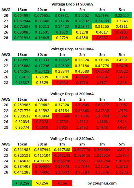
With contact resistance taken into account, it can be seen that it is difficult to meet requirements at high currents of 2A and 2.4A. As a result, cables only up to about 50cm can be used with 24AWG, or maybe even 1m with boosted source voltage. This is most significant for tablets.
For smartphones, with a requirement closer to 1A, 24AWG wires up to 2m could be sufficient, or 1m at 26AWG, and 50cm at 28AWG.
However, at 500mA (the original spec), it can be seen that it is possible to meet the stringent USB voltage requirement at every length with 20AWG wire, and 2m with 24AWG (probably by design).
The disadvantage of pushing more current at low voltages is very clear – the resistance causes power loss very quickly!
A corollary of this is that if you have a 3m cable, of 24AWG, then it’s likely your charge current is not going to exceed 1A (it’s probably 500mA-1A) purely because of the voltage drop that is caused by the cable.
Without Contact Resistance
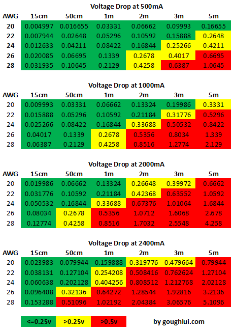
If we assume that connector resistance isn’t part of the equation, and look at the wires itself, the situation is a little less stringent, at high currents, but still illustrates the difficulty in keeping voltage drop under control.
One caveat of this, is that some vendors have realized the issue and decided to push the output voltage up to 5.1v or 5.2v, which is still within USB specification but allows for an extra 0.1-0.2v voltage drop. This is a potentially nice feature as it means the requirements on the cables are slightly relaxed (i.e. maybe even 0.7v voltage drop is tolerable).
It is also possible to see higher charge currents at the expense of voltage drop when the cell is fully discharged at 3v, as a ~3.2v input would be enough to start charging. Likewise, as the cell reaches full charge, the current tapers off, thus reducing the voltage drop. This might be happening already with some cables “pushing” what is possible. You know when it’s pushed too far when it doesn’t consistently charge fully (i.e. stuck at 94%, when eliminating all other issues).
Depending on who makes your cables, it might be possible to determine what sort of wires your cable is made out of. Ever seen the text on the side of your cable? Well, here’s a quick primer on what to look for.

The two cables above are pretty much equivalent. The top cable says 28AWG/1PR AND 24AWG/2C, and the bottom cable says 28AWG/1P+24AWG/2C.
What this means is that the cable is made of one data pair of 28AWG thickness, and two conductors (that carry positive and negative) of 24AWG thickness. Remember, the larger the AWG number, the thinner the wire.
The data pair thickness really is unimportant when it comes to charging, so just look for the AWG attached to the conductors. The 24AWG thickness is pretty common stuff.

That being said, many of the cheaper cables utilize 28AWG/1P+28AWG/2C. This isn’t the best stuff for charging.

It’s possible to be surprised – I had to look hard to find this one which is 28AWG/1P 22AWG/2C. I’ve also seen 26AWG used, but 20AWG is almost impossible to find but is referenced by the USB standards.
Unfortunately, many newer cables are not marked at all as to their composition, and in the case of some cheaper cables, it can be suspicious as they often utilize non-type-approved cables of custom construction, or leverage “audio” grade cable without the appropriate twisting or shielding for USB operation. These cables still often work, but poorly in RF/EMI harsh environments, and often have thinner conductors, but this is not a given as many OEM cables are unmarked as well.
You cannot tell the thickness of the wire within just by measuring the external diameter of the cable either. In the case of the cables examined above, all three have extremely similar external outer diameters, but the wire thickness inside is obviously different. The printing itself could be faked as well, you never know.
Other problems can include low quality connectors which don’t fit well and exhibit high contact resistance because of poor quality plating.
Unfortunately, direct measurement of the resistance of the cable is complicated. This is because of the low resistance of the assembly itself – below 2 ohms – and resistance contributions of the connectors themselves which may make it less easy to quantify the cable resistance accurately.
An attempt can be made by making a custom rig with a USB A Female end and a compatible mating connector for the other end of the cable, and running a known current (say, 2A) through it to measure the voltage drop.
However, for most concerned users, an easier method can be to try measuring the charging rate of the device by noting the amount of charge accumulated from flat after an hour or hour and a half of charging. In the case of problematic cable, there will be a significant difference.
If you want to avoid any charging problems, it’s always easiest just to stick with the OEM charger and cable. Replacement of chargers with other models may result in incompatible signalling that can cause slow charging.
However, if you are going to replace your cable with an aftermarket cable, it would be best to see if you can find a cable with the thickest possible conductors for the power. If that isn’t possible, stick with short (to very short) lengths, as that always works.
It’s not possible to be sure of the thickness of the wire just by the external appearance – printings can be forged, insulation can be made thicker (quite common). Likewise, it’s not possible to easily directly measure the resistance by using a regular multimeter due to the complication of the connectors, and the very low resistances (sub 2 ohms) involved.
If you really need to have a longer cable, consider extending the primary side using a mains extension cable instead.
However, I think it’s clear that by pushing the current levels through USB to higher levels than originally intended, we are losing efficiency and reaching the limits of low-voltage power distribution. That’s why, the USB power delivery standard is opting for higher voltages.
Source: https://goughlui.com/2014/10/01/usb-cable-resistance-why-your-phonetablet-might-be-charging-slow/