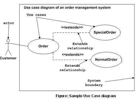
Dynamic behavior means the behavior of the system when it is running/operating.
5 diagrams to model Dynamic behavior :
- Use Case
- activity
- sequence
- collaboration
- Statechart
Some internal or external factors (actors) for making the interaction.
Use case diagrams consists of :
- actors
- use cases
- their relationships
The diagram is used to model the system/subsystem of an application.
A single use case diagram captures a particular functionality of a system. Hence to model the entire system, a number of use case diagrams are used.
Use case diagrams are used to gather the requirements of a system including internal and external influences. These requirements are mostly design requirements. Hence, when a system is analyzed to gather its functionalities, use cases are prepared and actors are identified.
When the initial task is complete, use case diagrams are modelled to present the outside view.
In brief, the purposes of use case diagrams can be said to be as follows −
- Used to gather the requirements of a system.
- Used to get an outside view of a system.
- Identify the external and internal factors influencing the system.
- Show the interaction among the requirements are actors.
Use cases diagrams = high-level requriement analysis of a system -> functionalities captured in use cases
Use cases = nothing but the system functionalities written in an organized manner
Actors = something that interacts with the system (a human user, some internal applications, external applications)
When draw an use case diagram :
- Functionalities to be presented as use cases
- Actors
- Relationships among the use cases and actors
Use case diagrams specify the events of a system and their flows. But use case diagram never describes how they are implemented. Use case diagram can be imagined as a black box where only the input, output, and the function of the black box is known.
