I recently completed a PSU replacement using the ReactiveMicro Universal PSU kit on an 1982 Apple ][+ unit. This is the build log of replacing the old PSU with the new one, as the old one was too aged and only accepted 120V AC (I live in a country that supplies 240V AC). This build log is a complement (not replacement) to the original ReactiveMicro Guide.

Detach the right side of the baseplate. This is the expected position of the PSU on the baseplate, but don't fasten the screws yet.
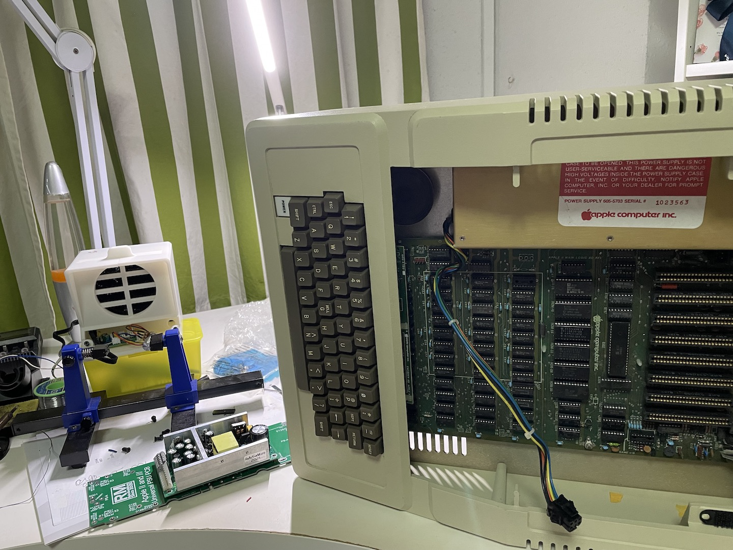
Extracting the PSU will require you to tilt the entire unit on its side and disconnect the power supply from the motherboard. Remove the old PSU from the case by unscrewing the 4 screws holding down the PSU. Unscrew the old PSU by removing a set of screws on its both sides. You may need another person to help you while you slide out the PSU from the chassis.
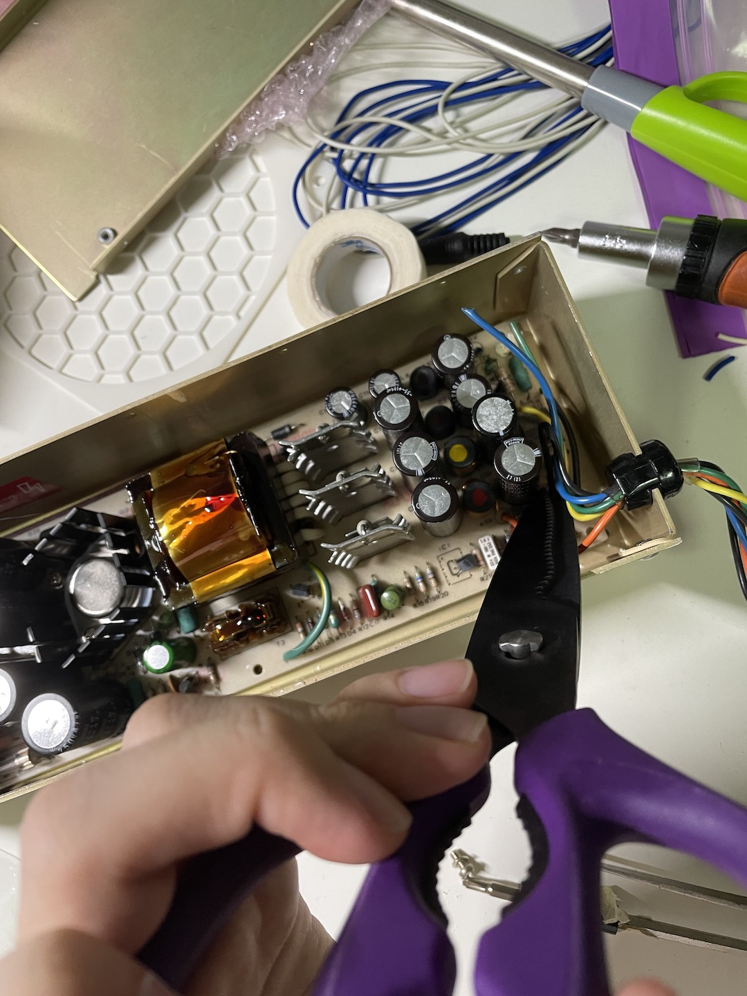
For my build, I had to cut and strip the cables (about 5mm) for the DC side as I did not buy the new power supply cables from ReactiveMicro. You might want to take pictures to ensure that you keep a record of the color vs voltage comparison. Cut the cables as close to the origin as possible.
Removing the old PSU circuit board was a challenge due to the large ferrite core blocking the way. I had to pry out the circuit board from the DC side and slide it outwards to avoid damaging the AC wires.

Screw down the baseplate to the PSU casing itself.

Wiring up was a bit of a challenge, given how short the AC side cables were. For my case, I had to solder extensions to the live and neutral wires and apply a heat shrink (insulation that shrinks after you apply heat to it). I originally tried the Scotchlok Quick Crimp Splice connector to bridge the two wires but it gave pretty intermittent connection after testing it with my multimeter, and I had to ditch it and ended up soldering it instead. If you wish to use the Scotchlok connectors, you almost certainly need a big plier to get it working.

After this, you can screw down the PSU to the baseplate and close up the PSU casing. You should test the power connectors with a multimeter to check if the voltages are correct so you don't fry your vintage computer.
IMG_1094.JPG
It's alive! All in all, the whole process took me about 3 hours on and off to complete it. With more experience I could possibly do it faster than I did the first time.
