
Turn on the sound to hear those satisfying clicks 💯
3dprintedcase.mp4

Simple Parametrized Snapfit Box in Onshape
- Design so that it can be printed with 0.6mm (faster) and 0.4mm nozzles (what most people have)
- Design so that everything is snap fit and no screws nor tools are needed
- Test print with 0.6mm nozzle and, e.g., PrusaSlicer FAST profile (0.35mm layer height; can do the layers for the snaps with higher precision if needed)
- Real prints with 0.6mm or 0.4mm nozzle and, e.g., PrusaSlicer NORMAL profile (0.20mm layer height)
- Use
#clearance= 0.2mm rigorously. If something doesn't work with the standard clearance, then the model is likely wrong!
#wall= 1.2mm (= 2 lines with 0.6mm nozzles, 3 lines with 0.4mm nozzles; NOTE: It may be possible to print 0.6mm lines using a 0.4mm nozzle; to be verified). NOTE: No clearance on the marked surface to the mating top case part!- A rectangle is drawn against the inner surface of the wall with width =
#width/2(half the width of the box) and height =1.5*#wall; this is extuded at 30 degrees angle (=60 degrees overhang; good 3D printers can do this) - Fillet to minimize filament blobs in these areas. Radius =
1.5*#wall/2 - Standoff up to`#clearance= = 0.2 mm
- Cutout on the XY plane allows for flexing, this is needed because otherwise this snap would break in Z. Avoid having to flex things in Z. Make the model flex in XY instead, like shown
- Fillet. Should be on opposite side as well
For something the size of a Raspberry Pi, The result is a very snug snap, almost bordering on being too hard to separate again. Maybe one could even get away with height #wall instead of 1.5*#wall? Being tested here
For smaller objects, a smaller wall size is sufficient.
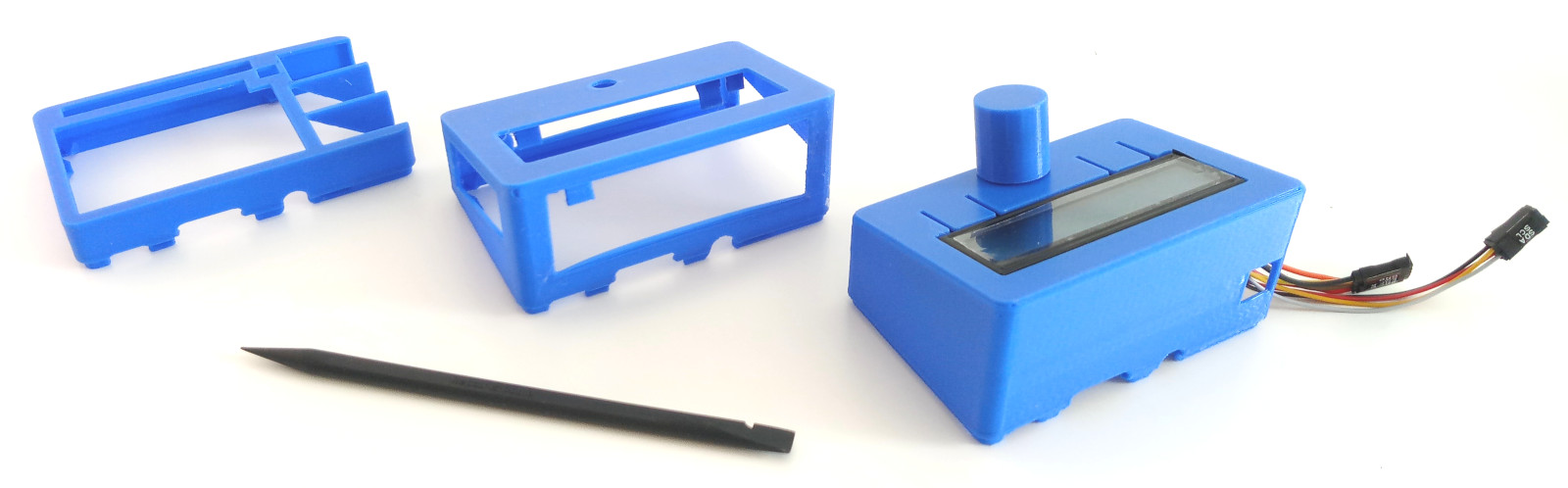
Quick and efficient prototyping using skeletons: Very lightweight, very fast to print, easy to spot what is going on because all solid walls have been removed. Once everything works, add the solid areas.
Even better, model regular closed walls and use the slicer to set a nice infill pattern (e.g., honeycomb) and no bottom and top layers.
- Step 1: Create a "tool" that is a simplified negative form of the PCB with xy clearance
- Step 2: Using the "tool", create the housing for the base PCB
- Step 3: To do variations (e.g., a LCD top cover rather than a standard one), create a new Onshape sketch/project and import the known working standard one using the "Derived" function, then modify until it does what it should
Raspberry Pi 4 sized cases
*#wall= 1.2mm,#clearance= 0.2mm- There is not much room for snaps/nubs, hence they are not very wide
- Nub height =
1.5*#wallwith 30 degrees angle (= 60 degrees overhang) = cannot easily open by hand. 45 degrees angle = easy to open by hand.